Network Representations
Network architects and administrators must be able to show what their networks will look like. They need to be able to easily see which components connect to other components, where they will be located, and how they will be connected. Diagrams of networks often use symbols, like those shown in the figure, to represent the different devices and connections that make up a network.
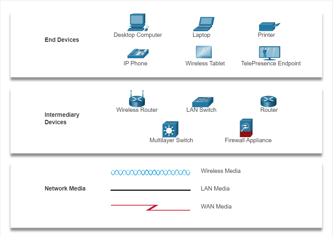
A diagram provides an easy way to understand how devices connect in a large network. This type of “picture” of a network is known as a topology diagram. The ability to recognize the logical representations of the physical networking components is critical to being able to visualize the organization and operation of a network.
In addition to these representations, specialized terminology is used to describe how each of these devices and media connect to each other:
- Network Interface Card (NIC) - A NIC physically connects the end device to the network.
- Physical Port - A connector or outlet on a networking device where the media connects to an end device or another networking device.
- Interface - Specialized ports on a networking device that connect to individual networks. Because routers connect networks, the ports on a router are referred to as network interfaces.
Note: The terms port and interface are often used interchangeably.
Topology Diagrams
Topology diagrams are mandatory documentation for anyone working with a network. They provide a visual map of how the network is connected. There are two types of topology diagrams: physical and logical.
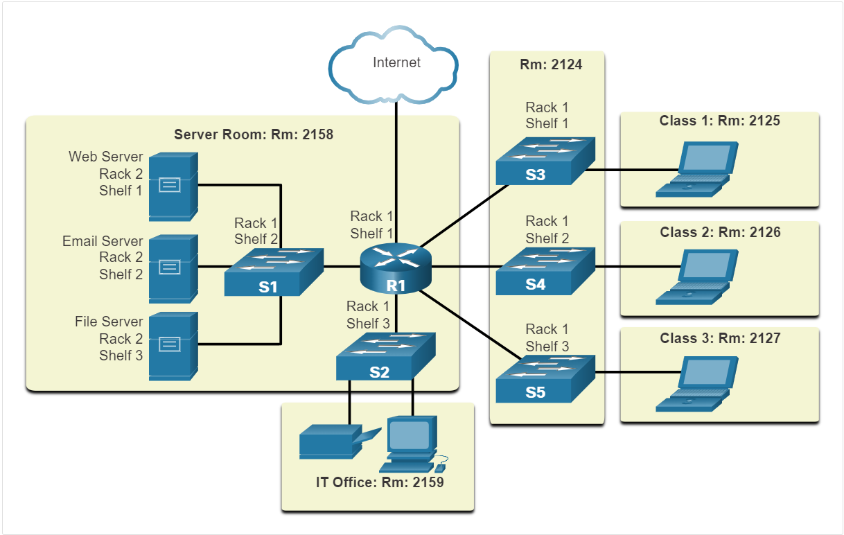
Physical Topology Diagrams
Physical topology diagrams illustrate the physical location of intermediary devices and cable installation, as shown in the figure. You can see that the rooms in which these devices are located are labeled in this physical topology.
Logical Topology Diagrams
Logical topology diagrams illustrate devices, ports, and the addressing scheme of the network, as shown in the figure. You can see which end devices are connected to which intermediary devices and what media is being used.
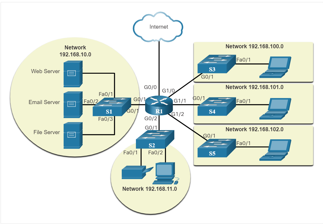
The topologies shown in the physical and logical diagrams are appropriate for your level of understanding at this point in the course. Search the internet for “network topology diagrams” to see some more complex examples. If you add the word “Cisco” to your search phrase, you will find many topologies using icons that are similar to what you have seen in these figures.